
CANDID C-05 - Surveillance Camera ENEO - Free user manual and instructions
Find the device manual for free CANDID C-05 ENEO in PDF.
| Product type | Day/night surveillance camera in outdoor housing |
| Brand | ENEO |
| Model | CANDID C-05 |
| Sensor | 1/3" Sony Super HAD Interline Transfer CCD (SS-1M) |
| Horizontal resolution | 480 TV lines |
| Sensitivity | 0.4 Lux (color) / 0.0044 Lux (black and white) |
| Lens | Varifocal DC, F1.2 ~ F260, 4.5 - 12.5 mm |
| Horizontal field of view | 57° ~ 22° |
| Electronic shutter | 1/2 to 1/100,000 sec |
| Digital Signal Processing (DSS) | 32x max. |
| Automatic Gain Control (AGC) | 28 dB max. |
| White balance | Automatic (ATW) 2000~8000K |
| Back Light Compensation (BLC) | Yes, switchable |
| Day/night mode | Motorized IR cut filter and automatic DSS mode |
| Anti-flicker | Switchable (FL), locks shutter to 1/120 s |
| Video output | 1 Vpp composite/CVBS, 75 Ω (BNC) |
| Power supply | 12 VDC (±20%) |
| Power consumption | Approx. 9 W |
| Protection rating | IP66/67 |
| Operating temperature | -30 °C to +40 °C |
| Weight | 1.2 kg |
| Housing material | Aluminium / plastic (Macrolone) |
| Sunshield | Yes |
| Cleaning | Soft dry cloth, no abrasive detergents |
| Safety | Do not disassemble, repair by authorized personnel |
| Package contents | Allen key 3 mm, mounting kit (manual, power supply optional) |
Frequently Asked Questions - CANDID C-05 ENEO
User questions about CANDID C-05 ENEO
0 question about this device. Answer the ones you know or ask your own.
Ask a new question about this device
Download the instructions for your Surveillance Camera in PDF format for free! Find your manual CANDID C-05 - ENEO and take your electronic device back in hand. On this page are published all the documents necessary for the use of your device. CANDID C-05 by ENEO.
USER MANUAL CANDID C-05 ENEO
Operating Instructions
1/3” Day/Night Video Cameras in a Weatherproof housing
Model Series: CANDID C-05 / CANDID C-06
Notice d'emploi
- Safety Instructions 12
- General Description 12
- Installation 13
3.1 Supplied Accessories 13
3.2 Opening the Housing for Adjusting the Angle of View 13
3.3 Joint between Housing and Articulated Arm 14
3.4 Connection Example when using Several Cameras 14 - Installation, Connection and Operation 15
4.1 Installing the Housing 15
4.2 Connection CableS 15
4.3 Connection using the Optional Power Supply Unit VHU-NT1 15 - Function Switchers 17
5.1 Positions and Functions of the Control Elements 17
5.2 Setting of the DIP Switchers 17 - Setup of the Image Sector 18
- Specifications 19
- Dimensional Drawings 36
Sommaire
1. Safety Instructions
- Please read these safety and operating instructions before putting the camera into operation.
- Keep the operating instructions in a safe place for later use.
- Do not operate the cameras beyond their specified temperature, humidity or power ratings.
- Pay attention when laying the connection cable and observe that the cable is not subject to heavy loads, kinks, or damaged and no moisture can get in. Do not attempt to disassemble the camera board from the housing.
- The unit may only be opened by an authorized personnel.
- The warranty becomes void if repairs are undertaken by unauthorized persons.
- Contact the supplier if any functional problems arise.
CAUTION: Do not fully tighten the fixing screws (10) until the camera is adjusted into its exact position. If the camera housing moves on the mounting arm after the fixing screws have been tightened, the housing may be subject to leaks.
Cleaning:
- Do not use strong or abrasive detergents when cleaning the housing and window (caution: plastic).
- Use a soft and dry cloth when cleaning. In case the dirt is hard to remove, use a mild detergent and wipe gently.
- Keep clean the window.
2. General Description
- 1/3" Day&Night Camera in Weatherproof Housing
- Resolution of 480 Horizontal Lines
- Sensitivity: 0,4Lux at colour / 0,0044Lux at BW (measured at F1,2); (Sens-up ON)
- Lens - CANDID C-05: F1,2 ~ F260 / 4,5 ~ 12,5mm; Vario-DC
- CANDID C-06: F1,3 ~ F240 / 7,5 ~ 50mm; Vario-DC
- High and Low Speed Shutter Control (ESC/DSS)
- Shutter Range: 1/2 to 1/100.000sec.
- Sensitivity Enhancement: up to 32x max.
Automatic Gain Control up to 28dB (AGC) - Backlight Compensation (BLC)
Automatic White Balance (ATW)
Day/Night, Flickerless Function ON/OFF switchable
Supply Voltage: 12VDC
Protection Rating: IP66/67
3. Installation
3.1 Supplied Accessories
- Power supply unit (optional)
- Operating instructions
- 3mm Allen wrench key, bag of screws
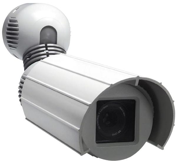
3.2 Opening the Housing for Adjusting the Angle of View
- Before the housing is opened, the sunshield (only for the weatherproof model) is to be moved so that the Allen screw (a) located in the housing middle section (1) is accessible.
- This screw is to be screwed into the housing by rotating it clockwise until it reaches the stop.
- The housing body (middle section) can then be taken off by pulling it forwards. The middle section of the housing is fixed to the camera mounting rail by an arrester cable.
- When handling the inner components the middle section can hang on the arrester cable.
- If required, the arrester cable can be hung on the camera mounting rail so that the middle section can be dismantled from the housing end and mounting arm.
Fig. 1
A Turning it clockwise = open
B Turning counterclockwise = close
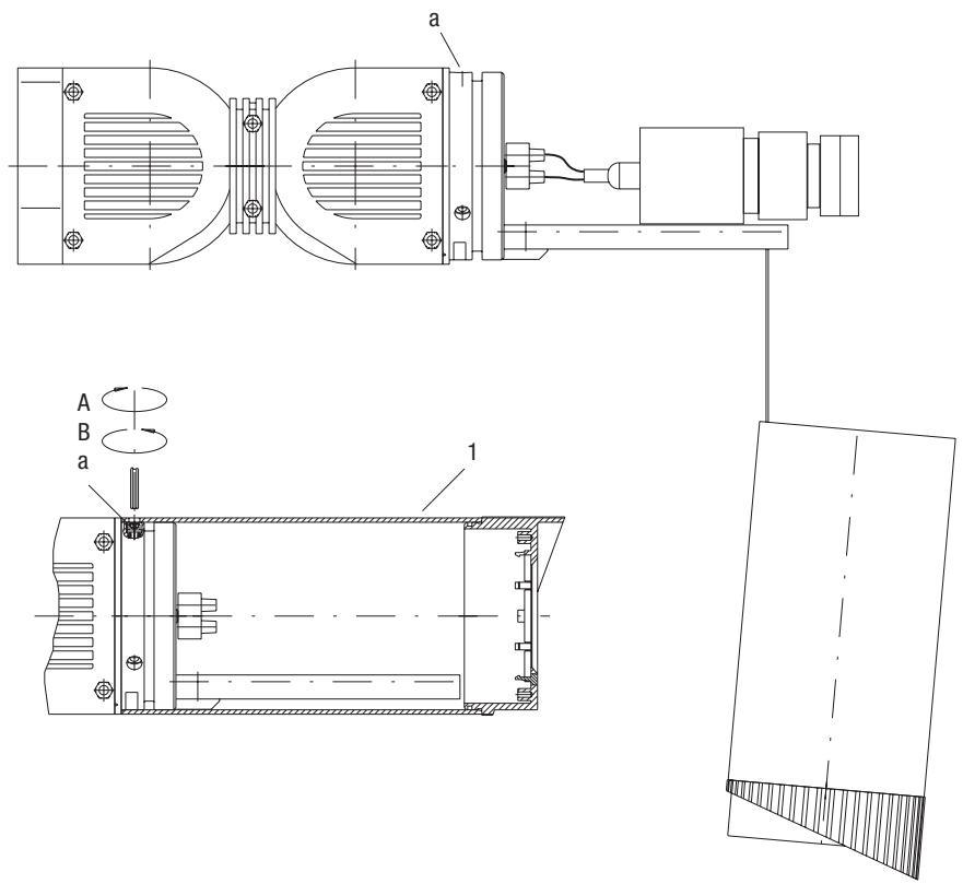
3.3 Joint between Housing and Articulated Arm
- The articulated arm is fitted to the housing rear wall (2) by 2 allen screws (b) and to the mounting plate (3) by Allen screws (c).
- When Allen screws (c) are undone the articulated arm can be rotated around axis A. Undoing screws (b) allows rotation around axis D.
- Rotation is possible around axis B as well as tilting around axis C by undoing Allen screws (d) on the locking ring (4).
- This design guarantees you nearly unlimited options when installing the articulated arm and therefore orienting and adjusting the camera.
- Each of the axes and the articulated arm are locked in place by tightening the screws (b-d). It should remain in the fixed condition a gap of at least 0.5mm
Fig. 2
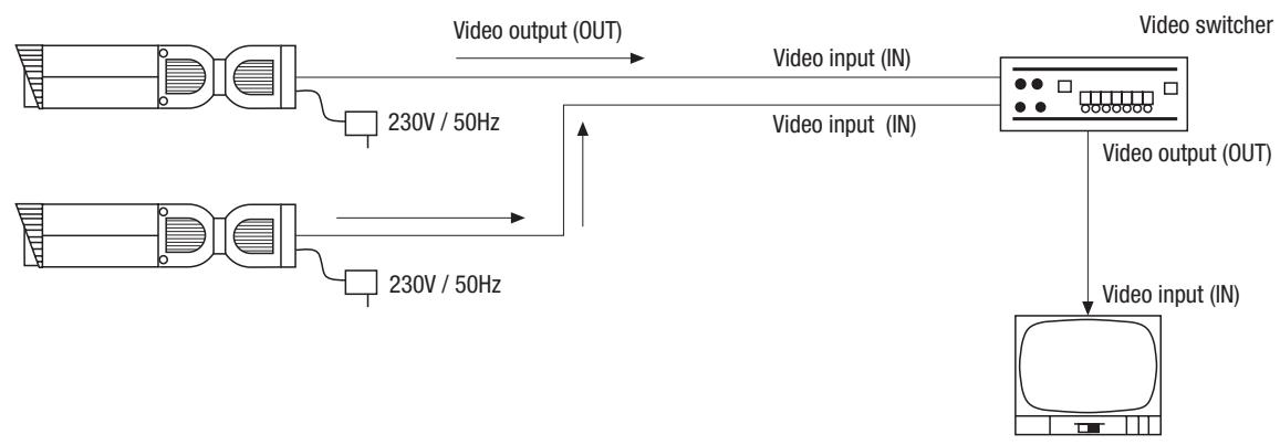
3.4 Connection Example when using Several Cameras
Always read the operating instructions for the devices and components carefully. Switch on the devices and components only after all the other connections have been carried out.
4. Installation, Connection and Operation
4.1 Installing the Housing
- To install the housing, undo the two Allen screws (c) (see fig. 2) and pull the mounting plate (3) from the housing.
- Fix the mounting plate to the internal wall, ceiling, external wall etc. using the enclosed fixing screws and plugs as appropriate. Before carrying this out, check that the surface is strong enough.
- The power supply and signal cables can be fed directly through the mounting plate and the cable entry (e) found at the side (see fig. 3). If necessary, the cable can again be fixed to the mounting plate with the enclosed cable clip in order to relieve strain.
NOTE: If the power supply unit that is provided as an optional extra is used, it is fitted to the surface instead of the mounting plate but following exactly the same instructions. In this case the mounting plate is not required.
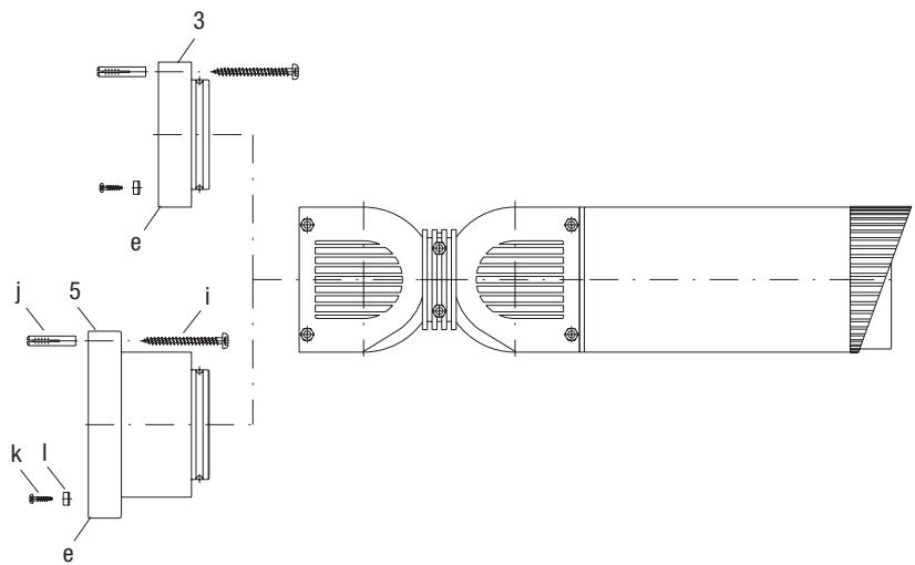
Fig. 3
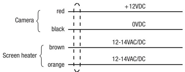
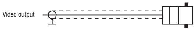
4.2 Connector Cables
4.3 Connection using the Optional Power Supply Unit VHU-NT1
The power supply base is an option supplied for the CANDID range of housings. It is designed for installation sites where a mains voltage supply is available. The power supply base is designed to be used exclusively with the CANDID range of housings and can only be operated with these housings.
Instead of the mounting plate (3), the mounting plate (5) with integrated power supply is fitted (see figs. 3 and 4) as described in section 4.1.
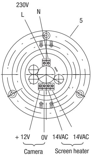
Fig. 4
VHU-NT1 Power supply
- The unit base with integrated power supply is installed with the round-head screw (i), wall plug (j), screws for the cable clip (k) and cable clip (l) which can be found in the accessories.
- The power supply and signal cables are fed through the cable bushing of the mounting plate with integrated power supply. The power supply cable is connected to the power supply terminal using the enclosed 4 pin connection block.
- The video cable can be extended in the articulated arm (BNC connection).
- Care must be taken that the connection cables are laid as centered as possible close to the power supply unit so that the range of movement of the articulated arm is not restricted.
- The power supply unit base should only be attached to a flat surface which is uniform to less than 1mm in the area where the base is attached.
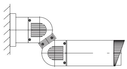
- Figure 6 shows the assembly location of the housing and power supply base. The power supply base is designed for hanging or horizontal installation. Intermediate positions are possible.
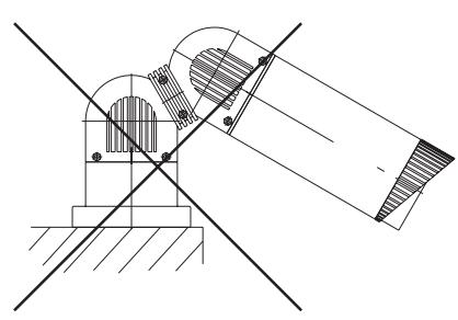
- It is not allowed to install the base as shown in figure 6. This way of installation is crossed out in the drawing.
- Care should be taken that the cable is fed from below through the breakout if the base is installed in a horizontal position.
- All cables entries must be sealed with standard sealing material (e.g. silicone) to comply with the protection class.
- The cable can also be fed directly from the wall to the power supply base.
- The connection between mains supply and connection block has to be double isolated. Please use the attached silicone isolation pipes.
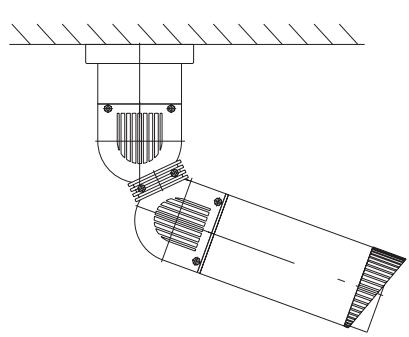
Fig. 5
Mounting position incl. power supply unit base
5. Function Switchers
5.1 Positions and functions of the Control Elements
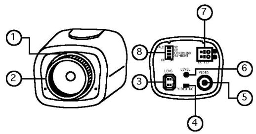
(1) Lens holder
(2) C mount adaptor
(3) Lens connector
(4) Lens select switch
(5) Video output BNC
(6) Iris level VR
(7) Power input terminal
(8) Function switch
Lens select switch
Switch must be set on DC position.
Video output BNC connector
1.0Vp-p/75ohms composite video signal is provided at this connector.
Iris level adjustment VR for DC drive lens
This potentiometer is used only if the camera is fitted with a DC drive auto iris lens. It is used to control the amount of light striking the CCD image sensor. Turn CW to increase or CCW to decrease the brightness.
This VR functions properly under the following condition:
- ESC/ALC switch -> ALC
- Lens select switch -> DC
DC drive auto iris lens is installed.
Power input terminal (screw terminal)
12VDC is supplied through this terminal (recommended power supply: min. 180mA
5.2 Setting of the DIP Switchers
SW 1: ALC / ESC (Default: ESC)
Used to select iris control mode.
Not needed because of the firmly inserted lens!
SW 2: BLC ON/OFF (Default: ON)
If the subject you wish to view is to dim because of a bright background, set the BLC switch to ON to compensate for the bright background. With BLC ON, the background brightness may saturate in some cases. This function may not operate properly if the object is too small compared to the area of the background. This function can be used with either the linear shutter (DSS or ELC mode).
SW 3: Flickerless ON/OFF (Default: OFF)
Under Flickerless ON mode, shutter is fixed to 1/120sec.
Flickerless mode is useful in areas where AC mains is 50Hz and TV systems is NTSC such like Japan or AC is 60Hz and TV system is PAL to reduce the flicker under the fluorescent lights. When FL is set to ON, the low light sensitivity is down about 30% .
SW 4: Day-Night (ICR+DSS) ON/OFF (Default: ON)
If set to ON, camera enables both of day-night functions (ICR & DSS) and performs its functions in sequence in accordance with the scene illumination.
If the light level of the scene goes down under the 1^st threshold, camera enters D/N mode by removing its IR cut filter and switching to B/W mode.
At 1^st stage of D/N mode, camera outputs the real time B/W video and can accept IR light.
If the light level becomes lower than 2^nd threshold, camera enters DSS mode and outputs the field integrated video. The frame refresh rate varies from 32 frames/sec(fastest) to 2 frames/sec (slowest) in accordance with the light level.
In case the light level increases, camera exits DSS and then ICR by returning its IR cut filter and switching to colour mode.
If set to OFF, camera operates just like a normal colour camera.
6 Setup of the Image Sector
- Pull off the middle section of the camera housing (see fig. 1).
Power up the camera and connect a monitor. - Open locking screw 2 (see fig. 6). Turn the ring to adjust the zoom setting.
Focus is adjusted by turning ring 1. - Tighten both locking screws 1 + 2 when adjustment is done.
NOTE: For a precise adjustment of cameras installed outside it is recommended to place a ND (Neutral Density) filter in front of the lens while settings are done. This opens up the iris and allows a setting which is constant at changing light conditions due to the narrower depth of field.
Fig. 6
① Focus ring (manual)
② Focal length adjustment (manual)
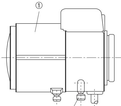
②
7. Specifications
| Type | CANDID C-05 | CANDID C-06 |
| EDP No. | 96077 | 96078 |
| System | CCIR/PAL | |
| Imager | 1/3" Sony Super HAD Interline Transfer CCD (SS-1M) | |
| Active Picture Elements | Approx. 440,000, (H) 752 x (V) 582 | |
| Signal Processing | Digital (DSP) | |
| Synchronization | Internal | |
| Signal-to-Noise Ratio | 48dB (AGC OFF) | |
| Horizontal Resolution | 480 TV lines | |
| Sensitivity | 0.4Lux at colour / 0.0044Lux at b&w (VT measurement result at F1.2) | |
| Shutter Speed | 1/2 ~ 100,000sec. | |
| Integration Rate | 32x | |
| Automatic Gain Control (AGC) | 28dB max. | |
| White Balance (ATW) | Automatic (2000 ~ 8000K) | |
| Backlight Compensation (BLC) | ON/OFF switchable | |
| IR Cut Filter | Motorized, switchable filter. Automatic function depend on the amount of light. Manual switching: see „switching-over colour/b&w". In removed filter position, the colour signal will be switched OFF | |
| External Adjustments | Day&Night, AGC, BLC, Flickerless ON/OFF, DC-iris control | |
| Video Output | 1Vp-p, (C)CVS, 75ohms | |
| Lens | F1.2 ~ F260 / 4.5 ~ 12.5mm, with DC-Iris controlled lens | F1,3 ~ F240 / 7,5 ~ 50mm, with DC-Iris controlled lens |
| Horizontal Angle of View | 57° ~ 52° | 36.6° ~ 5.64° |
| Minimum Object Distance (M.O.D.) | 0.3m | 0.4m |
| Window Heater | 12V, thermostatically controlled | |
| Cable Connection | Wiring for video and voltage supply made, accessible from outside | |
| Housing | Aluminium with plastic front and back (Makrolon) | |
| Sunshield | Yes | |
| Colour | RAL 9016 (Body and sunshield) RAL 7035 (Front and back) RAL 7037 (Inner ball, fixing ring) | |
| Protection Rating | IP66/67 | |
| Supply Voltage | 12VDC (±20%) | |
| Power Consumption | Approx. 9watts | |
| Temperature Range | -30°C ~ +40°C | |
| Dimensions | See drawing | |
| Weight | 1.2kg | |
| Parts Supplied | 3mm Allen wrench key, Bag of screws | |
Accessories
| EDP No. | Description |
| 73546 | Pole Mount Adapter for VHU Housing |
| 79494 | Power Supply Unit for Candid Housing |
8. Dimensional Drawings
See page 36
BN1: ALC/ESC (por defecto: ESC)
eneo® is a registered trademark of Videor Technical E. Hartig GmbH Exclusive distribution through specialised trade channels only.
Technical changes reserved.
Copyright by VIDEOR TECHNICAL 09/06